
A perfectly drafted patent application can still stall over a margin that is a few millimeters too narrow. It happens more often than most applicants expect. The claims are strong, the specification is thorough, and then an objection arrives because a reference number is too small or a sheet is numbered in the wrong place.

Understanding the USPTO patent drawing requirements before you file saves time, money, and prosecution headaches. This guide explains the formatting rules that examiners actually enforce, shows where each rule comes from, and gives you a practical workflow for producing a clean, compliant drawing set the first time.
Quick Answer: What Are USPTO Patent Drawing Requirements?
USPTO patent drawing requirements are the legal and formatting rules that govern how drawings must look when filed with a patent application. They appear mainly in 37 CFR 1.81 through 1.84 and in Section 608.02 of the Manual of Patent Examining Procedure (MPEP). The rules cover paper size, margins, line quality, lettering, view numbering, reference characters, shading, and which features the drawings must show.
The short version:
- Drawings must show every feature recited in the claims.
- Lines must be black, dark, clean, and uniformly thick.
- Reference characters must be at least 0.32 cm (1/8 inch) tall.
- Sheets must respect fixed margins on A4 or 8.5 x 11 inch paper.
- Every reference number in the drawings must appear in the specification, and the reverse must also hold true.
Keep those five points in mind. The rest of this article explains how to apply them and how to avoid the objections that slow examination down.
Why the Drawings in Your Patent Application Matter
Drawings are not decoration. Under 35 U.S.C. 113, an applicant must furnish a drawing where it is necessary for understanding the subject matter to be patented. For most mechanical, electrical, and software-related inventions, that means drawings are effectively mandatory.
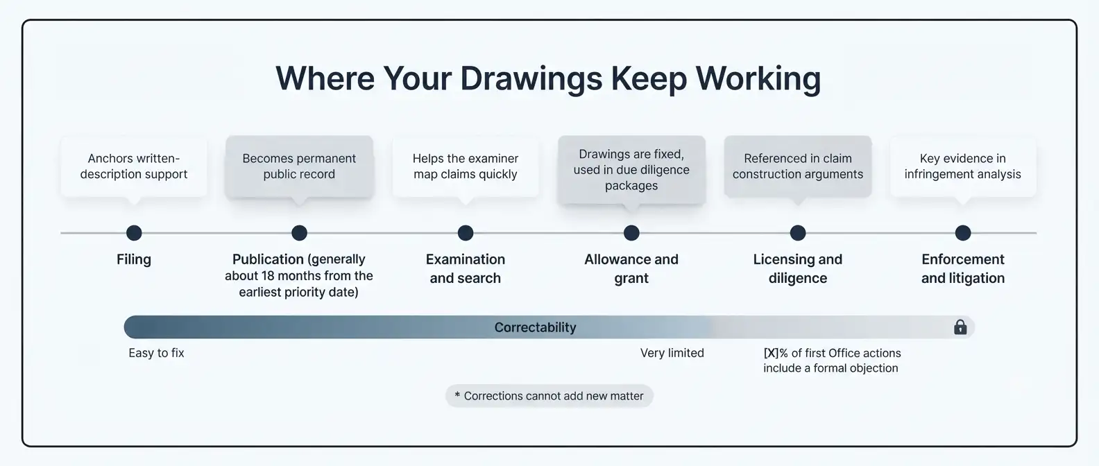
They also do real legal work. First, drawings form part of the original disclosure, so they can support claim language later. Second, they help the examiner understand the invention quickly. Third, they become part of the published patent, which means sloppy drawings stay in the public record permanently.
Additionally, the rules limit what you can do after filing. Because new matter cannot be added to an application, you cannot fix a missing feature in a drawing later by simply drawing it in. Therefore, getting the drawings right at the start protects your priority date and your claim scope.
The Practical Cost of Getting Drawings Wrong
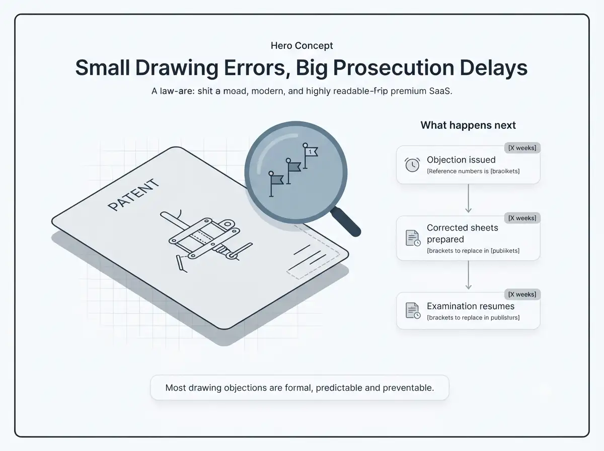
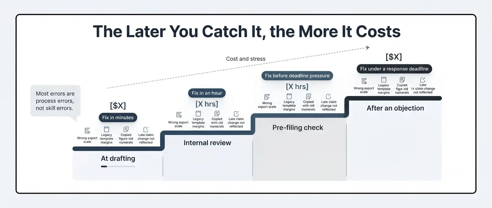
A drawing objection rarely kills an application. However, it creates friction that adds up:
- A response deadline you did not plan for.
- Extra billable hours for corrected sheets.
- Delays while the examiner waits for compliant drawings before allowing the case.
- Risk of a missed reply date if the objection is buried inside a larger Office action.
If your team already handles high volumes of filings, a single recurring drawing error can repeat across dozens of matters. That is why a documented review step matters. Our article on a multi-layered quality control workflow for patent docketing shows how a second-pair-of-eyes approach catches routine errors before they reach the USPTO.
Where the USPTO Patent Drawing Rules Actually Live
Before you memorize any numbers, it helps to know which source controls what. Many drawing mistakes come from relying on secondhand summaries instead of the rule text.
| Source | What it covers | Why it matters |
|---|---|---|
| 37 CFR 1.81 | When drawings may be submitted | Sets timing and the basic duty to file drawings |
| 37 CFR 1.83 | Content of drawings | Requires every claimed feature to be shown |
| 37 CFR 1.84 | Standards for drawings | Controls format, margins, lines, numbering, color |
| 37 CFR 1.121(d) | Amending drawings | Governs replacement and new sheets |
| MPEP 608.02 | Examiner guidance on drawings | Shows how examiners apply the rules in practice |
| MPEP 1503.02 | Design patent drawings | Adds view and line conventions for designs |
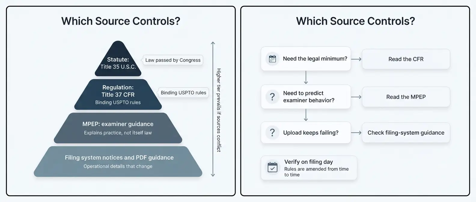
In practice, 37 CFR 1.84 is the rule set you will consult most. The MPEP, meanwhile, tells you how examiners interpret gray areas. When the two seem to conflict, the regulation controls.
Pro tip: Bookmark the eCFR version of Section 1.84 and check its “last amended” date. The rules change occasionally, and an outdated checklist is a common source of avoidable objections.
The Formatting Rules Examiners Enforce Most Often
Not every rule in Section 1.84 triggers objections with equal frequency. In our experience reviewing drawing sets for law firms and corporate IP departments, the same handful of issues appear again and again. Let us walk through them in the order you would encounter them while preparing a sheet.
Paper Size, Margins, and the Usable “Sight” Area
Drawing sheets must be a single, standard size. The USPTO accepts either A4 (21.0 cm x 29.7 cm) or letter size (8.5 x 11 inches). Do not mix sizes within one application.
Each sheet must leave blank margins on all four sides. All figures, numbers, and text must sit inside the remaining “sight” area.
| Margin | Minimum measurement |
|---|---|
| Top | 2.5 cm (1 inch) |
| Left | 2.5 cm (1 inch) |
| Right | 1.5 cm (5/8 inch) |
| Bottom | 1.0 cm (3/8 inch) |
The maximum sight area is 17.0 cm x 26.2 cm on A4 paper and 17.6 cm x 24.4 cm on letter paper. Notice that the margins are not symmetrical. Many first-time drafters center the figure on the page and accidentally violate the right or bottom margin.
Furthermore, the top margin has a job to do. It holds the sheet number and any identifying information, so do not treat it as wasted space.
Black Ink, Line Quality, and Reproduction
Section 1.84(l) sets the standard: every line, number, and letter must be durable, clean, black, sufficiently dense and dark, and uniformly thick and well defined. The rule applies to fine lines, shading, and the lines that represent cut surfaces in sectional views.
In modern practice, almost everyone files drawings electronically. Even so, the same standard applies to the scanned or exported image. Examiners flag drawings that show:
- Gray or faint lines that will not reproduce well in the printed patent.
- Jagged or pixelated edges from a low-resolution export.
- Broken lines caused by aggressive image compression.
- Background shading, scanner shadows, or stray marks.
Lines of different thickness are allowed when the difference has meaning, for example a heavier outline for the main body and lighter lines for hidden detail. However, the difference should be deliberate and consistent from figure to figure.
Quick tip: Export drawings as vector-based PDF whenever possible. Vector lines stay crisp when the USPTO reduces the sheet for publication.
Scale and Legibility After Reduction
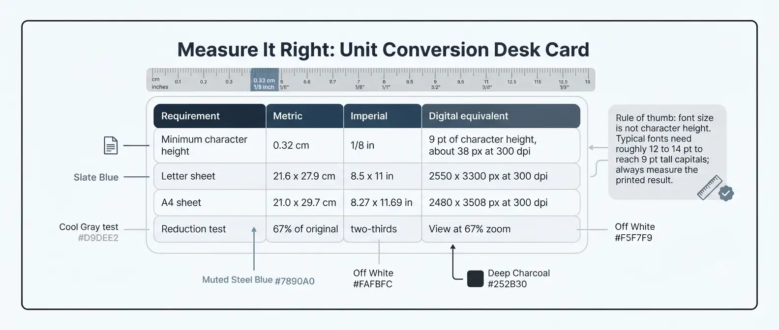
The USPTO reproduces drawings at a reduced size. Section 1.84(k) therefore requires the scale to be large enough to show the mechanism without crowding, even when the drawing is reduced to two-thirds of its original size.
A simple test works well. Print the sheet, shrink it to about 67 percent, and read it. If reference numbers blur together or fine lines disappear, the drawing fails the reduction test. In that case, either enlarge the key part with a separate detail view or simplify the figure.
Reference Characters, Numbers, and Lettering
Reference characters are the numerals and letters that connect a drawing to the specification. The rules are strict because these marks are how a reader matches a structure to its description.
Under Section 1.84(p), these points matter most:
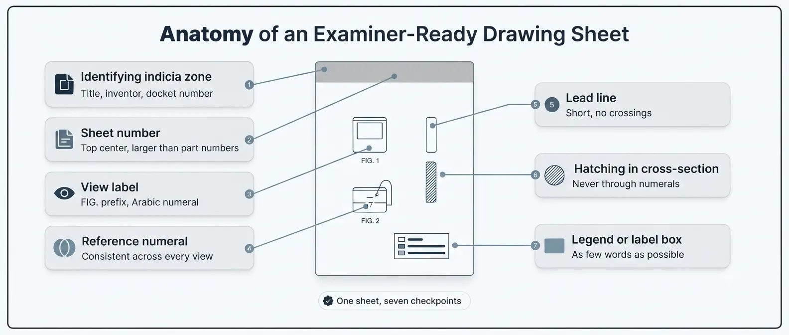
- Minimum height: Numbers, letters, and reference characters must be at least 0.32 cm (1/8 inch) tall.
- Plain and legible: Use a simple typeface. Avoid ornate fonts, and do not enclose reference characters in brackets, inverted commas, or outlines.
- Consistency: Use the same character for the same part across all views. Do not label one element “12” in FIG. 1 and “14” in FIG. 3.
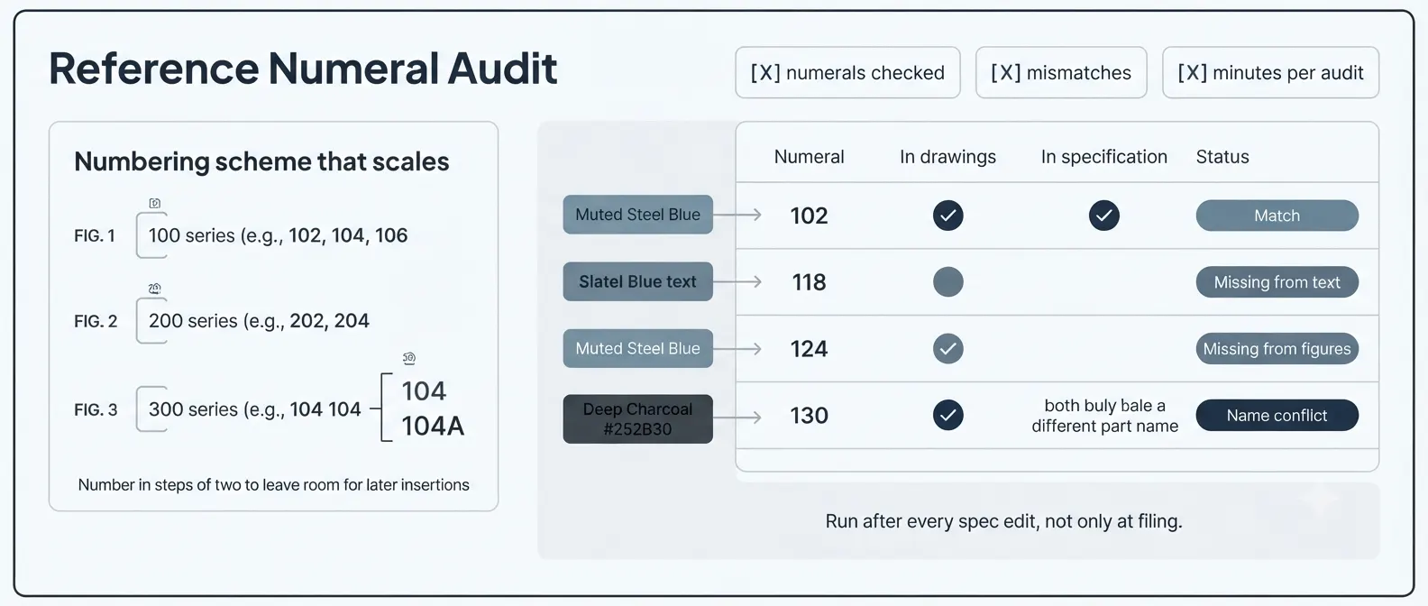
- Two-way match: Reference characters mentioned in the description must appear in the drawings, and reference characters not mentioned in the description should not appear in the drawings.
- Orientation: Place characters so the reader can read them without rotating the sheet, following the direction of the view.
The two-way match rule catches a surprising number of applications. It usually happens when the specification gets revised late in drafting and the drawings do not get updated. We cover this cross-check in more detail below.
Numbering Views and Sheets
Two different numbering systems apply, and people confuse them constantly.
View numbers identify each figure. Under Section 1.84(u), view numbers must be preceded by the abbreviation “FIG.” and should use Arabic numerals. Partial views that together form one complete view take the same number followed by a capital letter, such as FIG. 3A and FIG. 3B. In addition, a single-view application should not number the view or use “FIG.” at all.
Sheet numbers identify each page of drawings. Under Section 1.84(t), sheets are numbered consecutively starting with 1, using two Arabic numerals separated by an oblique line, for example “1/5” and “2/5”. The sheet number sits in the middle of the top of the sheet, but not in the margin. It must be larger than the reference characters so no one mistakes it for a part number.
Here is the difference at a glance:
| Feature | View number | Sheet number |
|---|---|---|
| Example | FIG. 2B | 3/7 |
| Rule source | 37 CFR 1.84(u) | 37 CFR 1.84(t) |
| Location | Near the view it identifies | Middle of the top of the sheet, within the sight area |
| Common error | Missing “FIG.” prefix, or numbering a single view | Placing the number inside the top margin or omitting the total |
Lead Lines, Arrows, and Reference Line Rules
Lead lines connect a reference character to the feature it identifies. Section 1.84(q) says they should start near the reference character and extend to the feature, and they must not cross each other or other lines where avoidable.
Arrows follow Section 1.84(r) and serve a few defined purposes:
- A free-standing arrow can show the direction of movement or flow.
- An arrow touching a line indicates a surface or the whole assembly.
- An arrow at the end of a lead line can point to the entire section toward which it points.
Examiners object when lead lines are ambiguous. For example, a line that ends near two adjacent parts leaves the reader guessing. Consequently, use a dot or arrow convention consistently and keep lead lines short and straight where possible.
Shading, Hatching, and Cross-Sections
Shading is encouraged when it helps the reader understand the shape of an object, but it must not reduce legibility. Section 1.84(m) also generally disallows solid black shading, except for special uses like bar graphs or color.
For sectional views, Section 1.84(h)(3) calls for hatching to indicate cut surfaces. Hatch lines should be diagonal, spaced far enough apart to read easily, and never so dense that they swallow reference characters. When a reference character must sit inside a hatched area, break the hatching around it.
Arrangement of Views on a Sheet
Section 1.84(i) sets three practical rules for layout:
- One view must not sit on top of, or inside the outline of, another view.
- All views on a sheet should face the same direction and read with the sheet held upright, where possible.
- If a wide view forces you to turn the sheet on its side, the top of the figure should point to the right-hand side of the sheet.
Also, text should always run horizontally from left to right, whether the sheet is upright or turned. The main exception is a graph that follows standard scientific convention for its axes.
Identifying Information in the Top Margin
Section 1.84(c) allows identifying indicia in the top margin of each sheet. Typically, this includes the title of the invention, the inventor’s name, and the application number or docket number. The marks must stay inside the top margin and must not intrude on the sight area.
Many firms add the docket number as a routine. It makes it easier to keep sheets matched to the correct matter, especially when several applications are in flight for the same client.
Quick-Reference Table: The Numbers to Check Before You File
Use this table as a fast pre-flight check. It does not replace the rule text, but it captures the measurable requirements that draw the most objections.
| Requirement | Rule to apply | Source |
|---|---|---|
| Sheet size | A4 (21.0 x 29.7 cm) or letter (8.5 x 11 in) | 37 CFR 1.84(f) |
| Top and left margins | 2.5 cm (1 in) each | 37 CFR 1.84(g) |
| Right margin | 1.5 cm (5/8 in) | 37 CFR 1.84(g) |
| Bottom margin | 1.0 cm (3/8 in) | 37 CFR 1.84(g) |
| Max sight, A4 | 17.0 x 26.2 cm | 37 CFR 1.84(g) |
| Max sight, letter | 17.6 x 24.4 cm | 37 CFR 1.84(g) |
| Character height | At least 0.32 cm (1/8 in) | 37 CFR 1.84(p)(3) |
| Line quality | Black, dense, uniform, well defined | 37 CFR 1.84(l) |
| View labels | “FIG.” plus Arabic numeral | 37 CFR 1.84(u) |
| Sheet labels | “1/5” style, top center, not in the margin | 37 CFR 1.84(t) |
Color Drawings and Photographs: When the USPTO Allows Them
The default is black-and-white line drawings. Nevertheless, Section 1.84(a)(2) allows color drawings and color photographs in limited circumstances, and Section 1.84(b) addresses black-and-white photographs.
Color Drawings
The USPTO accepts color drawings only when color is the only practical way to show the invention. To use them, you generally must:
- File a petition asking the Office to accept the color drawings.
- Pay the applicable petition fee, which you should confirm on the current USPTO fee schedule.
- Supply the required number of color drawing sets.
- Add a statement to the specification, at the start of the brief description of the drawings, noting that the file contains at least one drawing executed in color.
Because rules and fees change, check the current version of Section 1.84(a)(2) before you file. A missing petition is one of the fastest ways to draw an objection.
Black-and-White Photographs
Photographs are not a substitute for drawings in most utility applications. Section 1.84(b) allows them only where drawings cannot adequately show the subject, such as crystalline structures, metallurgical microstructures, textile fabrics, grain structures, and ornamental effects. If you file photographs, they must have enough contrast and detail to reproduce clearly.
Design Applications
Design applications follow different conventions. The design itself is the claim, so photographs or drawings are the entire disclosure. You may submit either photographs or drawings, but generally not both for the same design. Read MPEP 1503.02 closely before filing.
What the Drawings Must Show: Content Rules Under 37 CFR 1.83
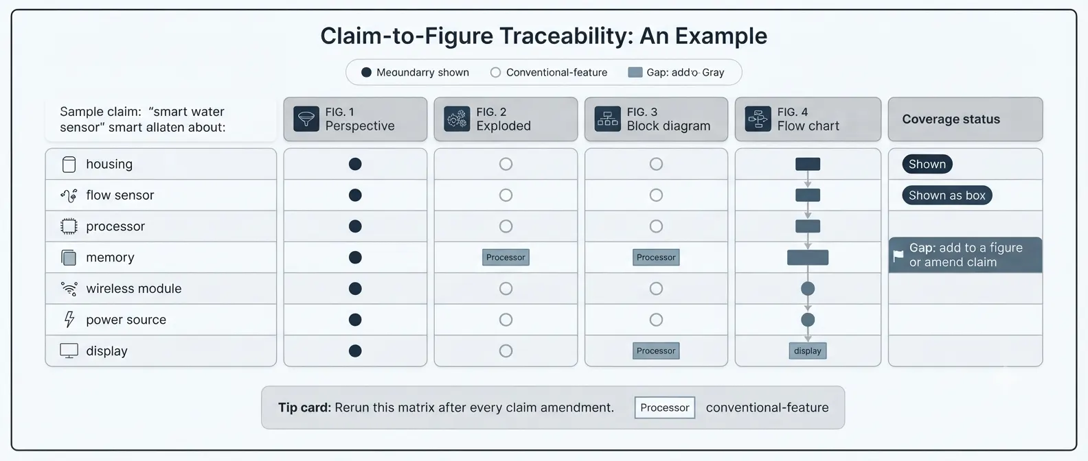
Formatting is only half the story. The other half is content. Section 1.83(a) states that the drawing in a nonprovisional application must show every feature of the invention specified in the claims.
That single sentence causes more Office action objections than any margin rule. It usually happens for two reasons:
- The claims were amended or added late, and no one updated the drawings.
- The specification describes an element the claims later recite, but no figure illustrates it.
Conventional Features and Labeled Boxes
You do not need to draw every well-known component in detail. Where detailed illustration is not essential to understand the invention, Section 1.83(a) allows a graphical drawing symbol or a labeled representation, such as a labeled rectangular box. Software, electronics, and networking inventions rely heavily on this convention.
For example, a block diagram can show a “processor,” a “memory,” and a “network interface” as labeled boxes. As a result, the drawing stays clean while still supporting claim language.
Legends and Prior Art Labels
Section 1.84(o) permits suitable descriptive legends, subject to approval by the Office, and requires them where the examiner needs them for understanding. Keep legends to as few words as possible. Where a figure illustrates prior art, label it clearly, and MPEP 608.02 explains how examiners expect that label to appear.
Flow charts, block diagrams, and schematic figures often need text labels inside the boxes. That is acceptable, provided the text meets the same height and legibility rules as reference characters.
Drawings for Provisional Applications
Provisional applications have a lighter formal burden. The USPTO does not examine a provisional, so it generally does not object to informal drawings. Still, the drawings must be clear enough to support the disclosure you later rely on for priority. If you plan to claim benefit of the provisional, draw it as carefully as you would a nonprovisional.
Keeping Drawings and Specification in Sync
A drawing set can meet every formatting rule and still draw an objection because it does not match the text. Two specification requirements tie directly to the drawings.
First, Section 1.74 requires a brief description of the several views of the drawings whenever drawings are present. Second, the detailed description should refer to each figure and each reference character by number.
A Simple Cross-Check Method
Try this three-pass method before every filing:
- List every figure in the drawings, then confirm each one has an entry in the brief description of the drawings.
- List every reference character that appears in the drawings, then search the specification for each one.
- List every reference character in the specification, then confirm it appears in at least one figure.
Any mismatch is a potential objection. In addition, run a fourth check against the claims: confirm each claimed element has a matching structure in at least one figure.
This process pairs naturally with the review discipline we describe in our post on preparing a request for continued examination, where accuracy across documents is equally critical.
Utility, Design, and Provisional Drawings Compared
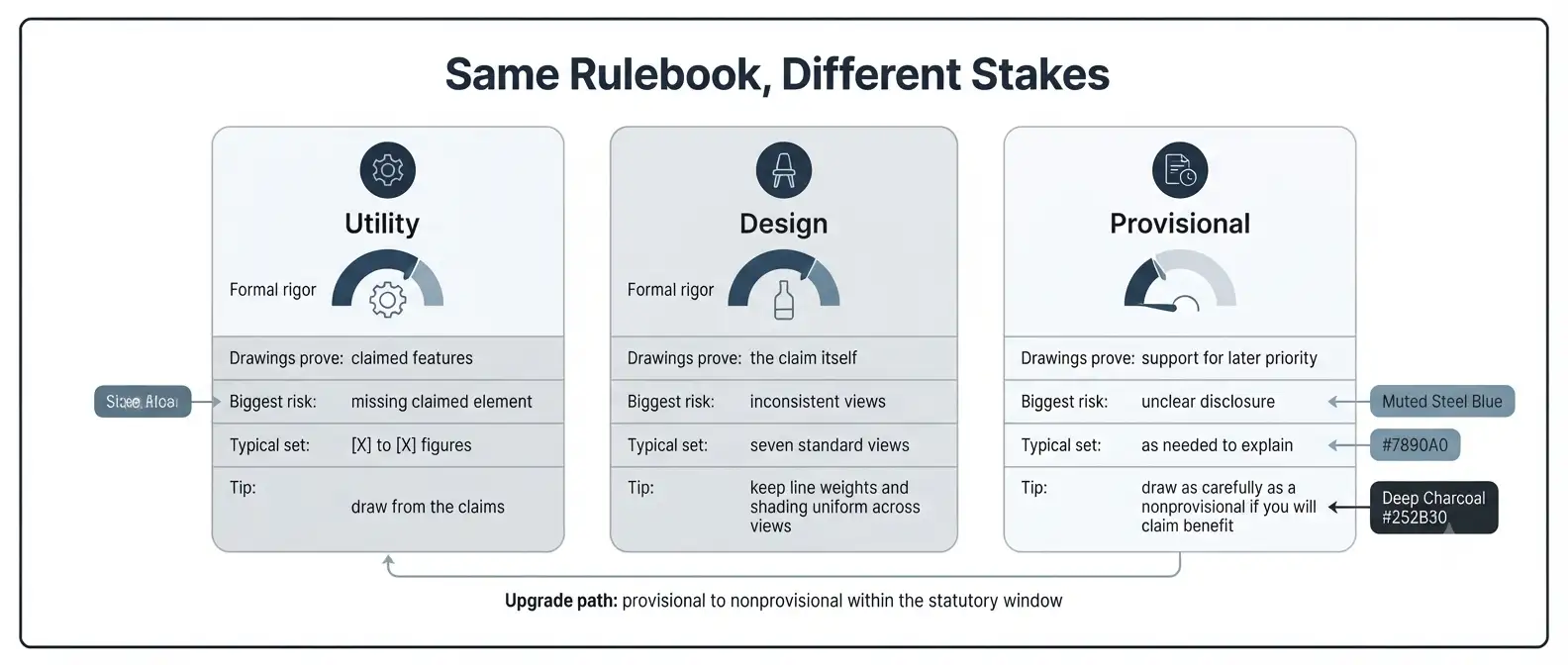
Different application types apply the drawing rules differently. This comparison helps you decide how much rigor each situation demands.
| Factor | Utility (nonprovisional) | Design | Provisional |
|---|---|---|---|
| Governing rules | 37 CFR 1.83 and 1.84; MPEP 608.02 | 37 CFR 1.84 plus MPEP 1503.02 | Formal drawing rules generally not enforced |
| Purpose of drawings | Illustrate every claimed feature | Define the claimed design itself | Support the disclosure for later priority |
| Photographs | Limited cases only | Allowed, but drawings and photos generally not mixed | Acceptable if clear |
| Typical views | Perspective, sectional, exploded, detail, flow | Perspective, front, rear, left, right, top, bottom | Whatever explains the invention |
| Broken lines | Used for hidden or environmental parts | Used to show unclaimed subject matter | Optional |
| Objection risk | High | High | Low, but priority risk if unclear |
The takeaway is simple. Utility and design drawings carry formal risk, while provisional drawings carry substantive risk. Treat all three seriously.
Filing Drawings Electronically Through Patent Center
Most applicants now file through the USPTO’s Patent Center. Electronic filing changes the format question slightly, but not the underlying rules.
Here are the practical points we check on every electronic submission:
- File format: Submit drawings as a PDF, and confirm every figure is on its own sheet within the drawing document.
- Fonts: Embed all fonts so text renders the same on the examiner’s screen.
- No security: Avoid password protection or restrictions that could block processing.
- Page count: Confirm the PDF page count equals the total in your sheet numbers, for example that “5/5” is the last page.
- Document code: Upload the drawings under the correct document description so the system routes them properly.
Also remember that drawings belong on separate sheets. Do not embed figures inside the text of the specification unless you have confirmed that approach is acceptable for your filing type.
If you manage a large docket, a dedicated intake step for drawings pays off. Our patent drawing services team handles this kind of pre-filing formatting review for firms that want a consistent, examiner-ready result.
Step-by-Step: How to Prepare a Compliant Patent Drawing Set

Follow this sequence to reduce rework. It works whether you draw in-house or brief an outside drafter.
- Start from the claims. List every element recited in the independent and dependent claims. Each one needs a home in at least one figure.
- Choose your views. Decide which perspective, sectional, exploded, detail, and flow figures best show each element.
- Set the sheet template. Create a page at A4 or letter size with the correct margins and a marked sight area.
- Draw in vector format. Use clean, uniform black lines and avoid gray fills or gradients.
- Assign reference numbers. Use consistent numerals, at least 0.32 cm tall, and keep the numbering logic predictable (for example, 100-series for FIG. 1).
- Add lead lines and arrows. Keep them short, non-crossing, and unambiguous.
- Label views and sheets. Add “FIG.” labels, then add sheet numbers such as “1/5” at the top center.
- Run the reduction test. Shrink the sheet to two-thirds size and confirm everything remains legible.
- Cross-check against the specification. Use the three-pass method described above.
- Export and inspect. Save a PDF with embedded fonts, then view it at full size and at reduced size.
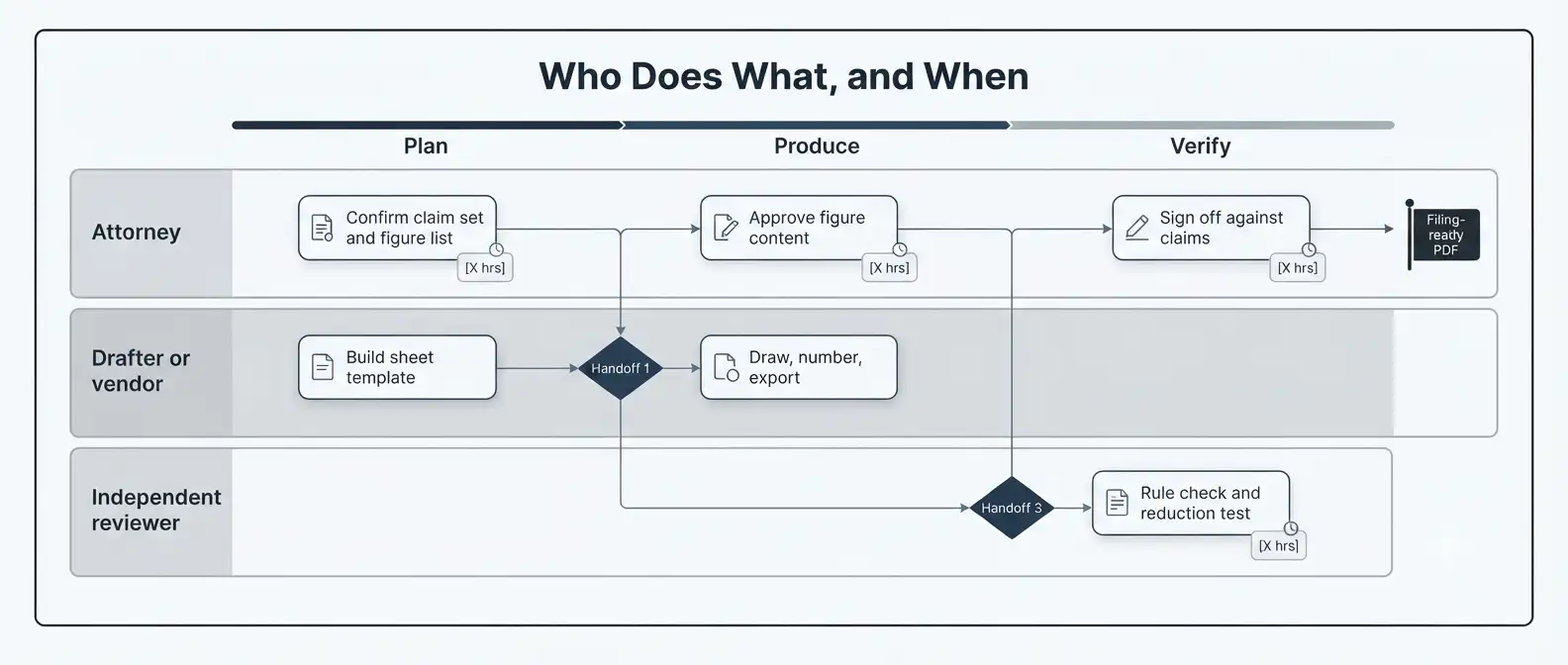
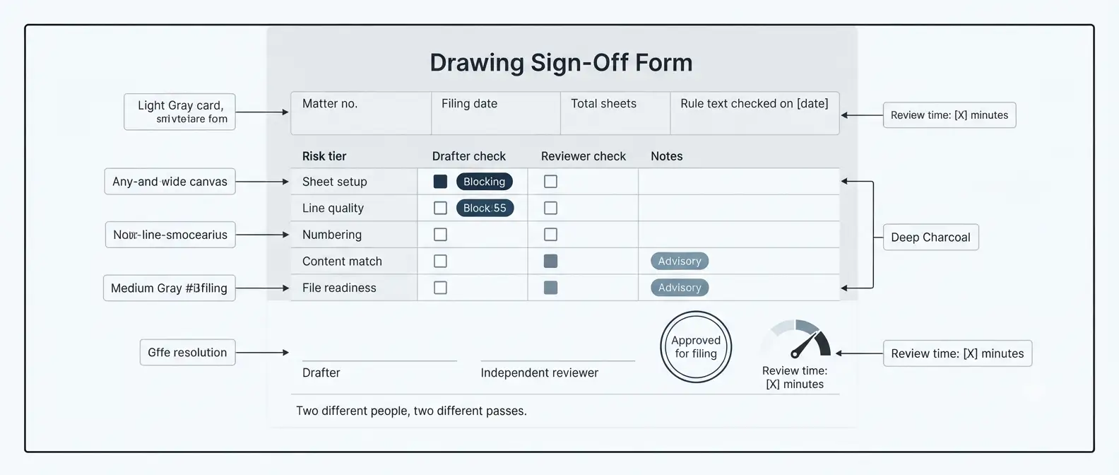
- Get a second review. Have a reviewer who did not create the drawings check them against Section 1.84.
Why step 11 matters: Drafters see what they intended to draw. Reviewers see what is actually on the page.
Common Mistakes That Trigger Drawing Objections
After reviewing many drawing sets, we see the same errors repeatedly. Fortunately, nearly all of them are preventable.
- Margins violated on the right or bottom. Drafters center the figure and forget the margins are uneven.
- Reference numbers under 0.32 cm. Text looks fine on a monitor but fails once printed.
- Missing “FIG.” prefix. Labels like “Figure 1” or just “1” do not follow Section 1.84(u).
- Sheet numbers in the wrong place. Numbers sit inside the top margin, or they omit the total.
- Numbering a single view. A one-figure application should not carry a figure number.
- Reference numbers that do not match the specification. This is the most common substantive mismatch.
- Claimed features missing from the figures. This often follows late claim amendments.
- Gray shading or gradients. These reproduce poorly and violate the line-quality rule.
- Text rotated or set vertically. Words must read left to right except in standard graph axes.
- Overcrowded figures. Details collapse when the sheet is reduced.
- Color used without a petition. Even a colored highlight can trigger an objection.
- Handwritten notes or stray marks. Scanned drawings often carry these.
Objection Reference Table
| Examiner objection | Likely cause | Typical fix |
|---|---|---|
| Drawings not in black ink or lines faint | Low-resolution scan, gray fills | Redraw in vector, use solid black |
| Reference character not mentioned in description | Specification edited after drawing | Add the character to the text or remove it from the figure |
| Claimed feature not shown | Late claim amendment | Add a figure or amend the claim (no new matter) |
| Sheet or view numbering improper | Wrong format or placement | Renumber per 1.84(t) and 1.84(u) |
| Text too small | Font size under 0.32 cm | Enlarge characters, rescale the figure |
| Margin violation | Content outside the sight area | Reposition or rescale the figure |
Responding to a Drawing Objection: Replacement Sheets Under 37 CFR 1.121(d)
Sometimes an objection arrives despite your best efforts. The correct response depends on what the examiner requires, but the mechanics are consistent.
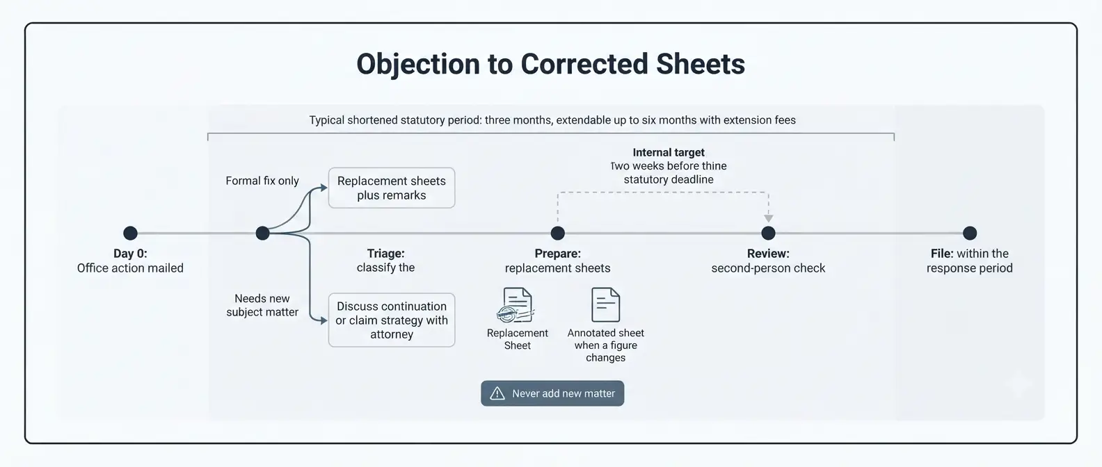
Under 37 CFR 1.121(d), you correct drawings by submitting a replacement sheet rather than marking up the original. Follow these steps:
- Read the objection carefully. Note exactly which figures and rules the examiner cites.
- Prepare a replacement sheet for every sheet that needs changes. Include all figures on that sheet, not just the corrected one.
- Label the sheet “Replacement Sheet” in the top margin, following the rule text.
- Add an annotated sheet marked to show changes when the amendment alters a figure, if the rules require it.
- Include a remarks section that identifies the changes and explains how they resolve the objection.
- Confirm no new matter appears in the corrected drawings.
- File within the response period so the reply is timely.
The new matter point deserves emphasis. A correction may fix a formality, but it may not add subject matter that the original application did not disclose. If a missing element requires new matter to fix, you may need a continuation or another strategy. Our comparison of an RCE versus a continuation application explains when each path fits.
When the objection is part of a larger Office action, coordinate the drawing fix with the substantive response. For teams that want support here, see our overview of Office action response support services.
Expert Tips From Real Drawing Review Work
These habits separate teams that rarely see drawing objections from those that see them regularly.
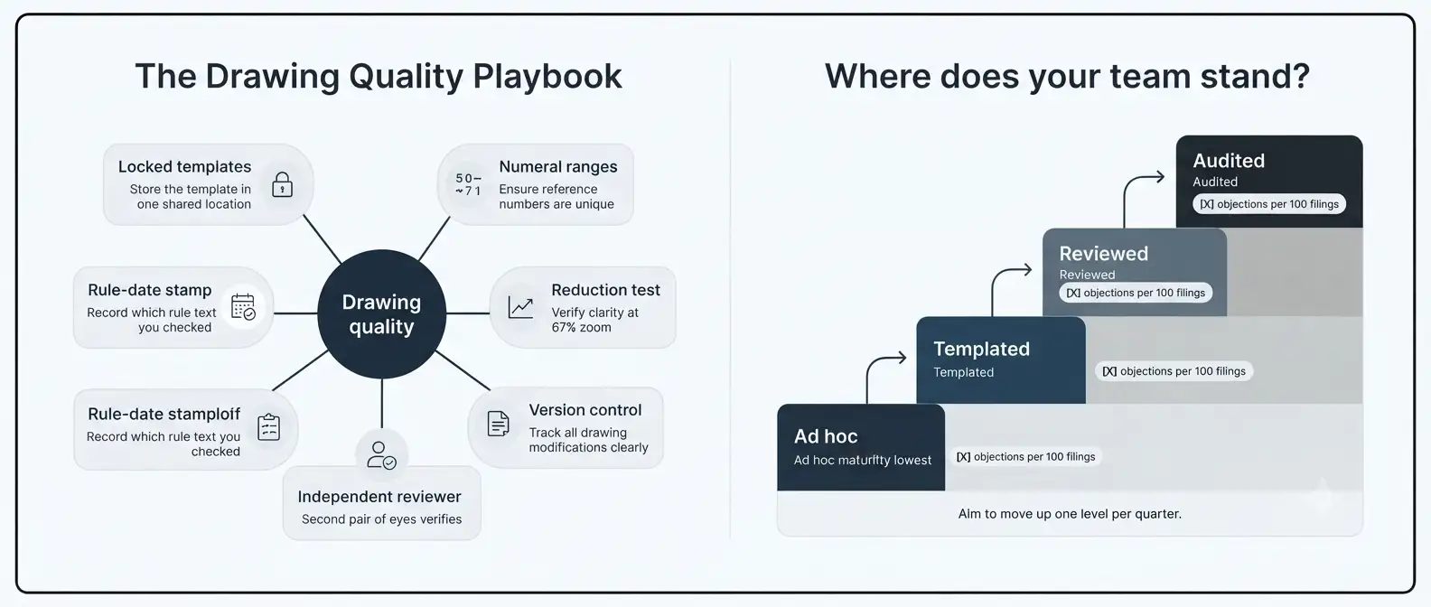
- Build a firm template. A locked sheet template with margins, sheet numbering placeholders, and font settings removes most formatting errors at the source.
- Draw for reduction, not for the screen. Always test at two-thirds size, because that is how the printed patent looks.
- Reserve number ranges. Assign 100s to FIG. 1, 200s to FIG. 2, and so on. This makes reference characters predictable and easy to audit.
- Freeze drawings only after the claims are stable. If claims are still moving, expect to revisit the figures.
- Track drawing changes in your docket. Log each version so you can prove which sheet was filed.
- Use flow charts sparingly. Each box label must meet the text-size rule, and too many boxes shrink the type.
- Keep an examiner-facing eye. Ask, “Could a busy examiner locate every claimed feature in under a minute?”
- Check the current rules on the day you file. Regulations and USPTO systems evolve, so verify against the eCFR rather than an old checklist.
For firms that outsource part of this workflow, vendor quality matters as much as drawing quality. Our IP vendor due diligence checklist helps you evaluate whether a provider follows a real review process.
Pre-Filing Checklist for USPTO Patent Drawing Requirements
Print this list, or paste it into your matter management system. Each item ties back to a rule discussed above.
Sheet setup
- All sheets use A4 or letter size, and no mixed sizes.
- Margins meet 2.5 cm top, 2.5 cm left, 1.5 cm right, 1.0 cm bottom.
- All content sits within the maximum sight area.
Line and text quality
- Every line is black, dark, uniform, and well defined.
- No gray fills, gradients, or scanner shadows appear.
- Reference characters are at least 0.32 cm tall.
- Text reads left to right, except for standard graph axes.
Numbering and labels
- Each view carries “FIG.” plus an Arabic numeral (or no number for a single view).
- Sheets are numbered in “1/5” format at the top center, inside the sight area.
- Identifying indicia, if used, sit in the top margin only.
Content and consistency
- Every claimed feature appears in at least one figure.
- Every reference character in the drawings appears in the specification.
- Every reference character in the specification appears in the drawings.
- The brief description of the drawings lists every figure.
- Prior art figures carry a clear label.
Special cases
- Any color drawing has a petition and specification statement.
- Any photograph fits an allowed category.
- Design views follow MPEP 1503.02.
Electronic filing
- The PDF has embedded fonts and no security restrictions.
- The PDF page count matches the sheet numbering.
When It Makes Sense to Outsource Patent Drawings
Some teams draw everything in-house. Others outsource part or all of it. Neither approach is wrong, but the decision should rest on a few practical signals.
Consider outside support when:
- Filing volume spikes and drafters cannot keep pace.
- Inventions need specialized illustration, such as exploded assemblies or complex flow charts.
- You want a consistent house style across many matters.
- A repeated objection pattern shows that your current process has a gap.
- Your attorneys should spend time on claims and strategy rather than sheet formatting.
Many teams also pair drawing support with broader paralegal help. If your docket is growing faster than your staff, our piece on signs your firm needs additional patent paralegal support offers a useful self-assessment. Likewise, if you are weighing remote help, read whether remote patent paralegal services are compliant with USPTO rules before you commit.
Drawings also connect to other filing tasks. For instance, IDS preparation and filing and PCT application services both depend on a clean, consistent drawing set, since foreign and international filings apply their own drawing standards on top of the USPTO rules.
Frequently Asked Questions About USPTO Patent Drawing Requirements
What are the basic USPTO patent drawing requirements?
The basic USPTO patent drawing requirements are black, uniformly thick lines; A4 or letter-size sheets with fixed margins; reference characters at least 0.32 cm tall; “FIG.” view labels; sheet numbers in “1/5” format; and drawings that show every claimed feature. Most of these rules live in 37 CFR 1.84.
What size should USPTO patent drawings be?
Drawings must be on A4 (21.0 x 29.7 cm) or letter-size (8.5 x 11 inches) sheets. Each sheet needs margins of 2.5 cm at the top and left, 1.5 cm on the right, and 1.0 cm at the bottom. Content must stay inside the sight area.
Can I use color drawings in a patent application?
Yes, but only in limited cases. Section 1.84(a)(2) requires a petition, the applicable fee, and a specification statement noting the color drawing. Use color only when black-and-white drawings cannot show the invention adequately.
Do patent drawings have to be in black and white?
In most cases, yes. Black-and-white line drawings are the default. Black-and-white photographs are allowed only where drawings cannot adequately show the subject, such as crystalline structures or textile fabrics.
What happens if my patent drawings do not meet USPTO requirements?
The examiner may object to the drawings and require corrected sheets. You typically respond with replacement sheets under 37 CFR 1.121(d) within the response period. The correction cannot add new matter.
Does every figure need a reference number?
Not every figure needs one, but every reference character in the specification must appear in the drawings, and every reference character in the drawings should appear in the specification. Clear, consistent reference numbers help examiners match structure to description.
Are the drawing rules the same for design patents?
No. Design applications follow Section 1.84 plus the specific guidance in MPEP 1503.02. Because the drawings define the claimed design, the views and line conventions matter even more.
Conclusion: Treat USPTO Patent Drawing Requirements as Part of Your Claim Strategy
The USPTO patent drawing requirements can look like a list of fussy formatting rules. In reality, they protect the value of your disclosure. Clean, complete, consistent drawings help examiners understand the invention, reduce objections, and preserve your options during prosecution.
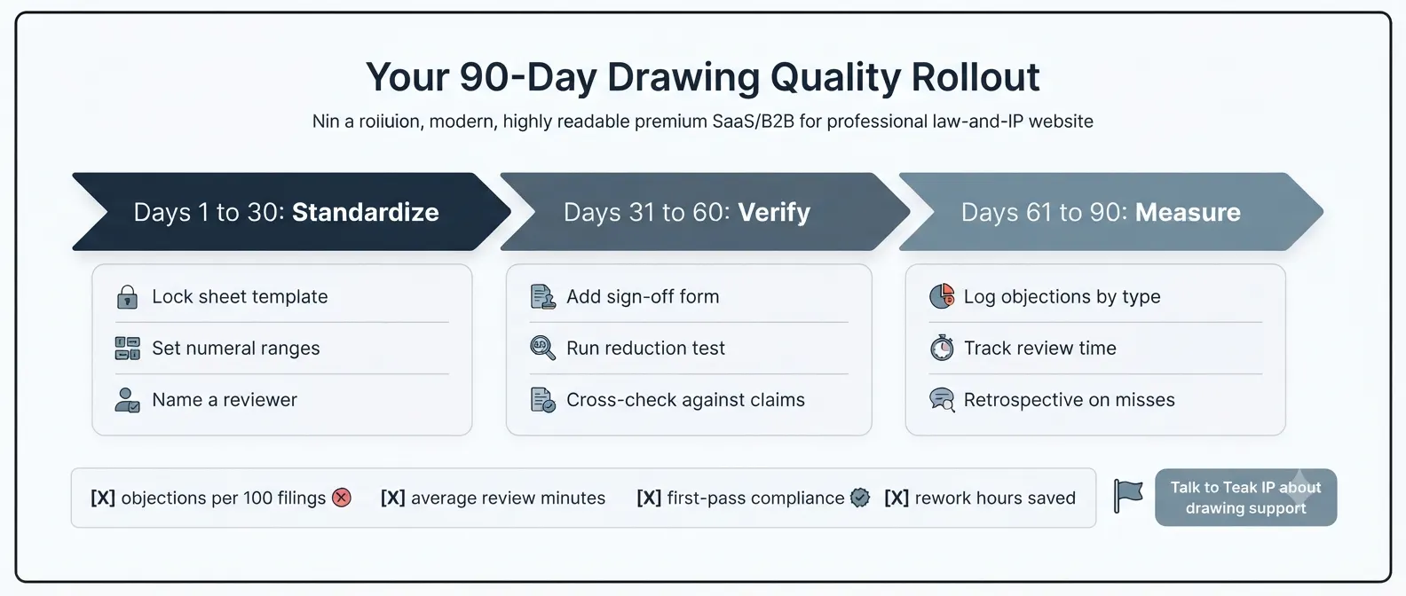
To recap, focus on five habits:
- Build drawings from the claims, so every claimed feature appears.
- Use a locked sheet template with the correct margins and numbering.
- Keep lines black, uniform, and legible at two-thirds size.
- Cross-check reference characters against the specification.
- Add a second review before you file.
Rules change, and examiners apply them with some variation, so always verify against the current 37 CFR 1.84 and MPEP 608.02 on the day you file.
If you would rather hand off the formatting work, Teak IP Services can help. Our U.S. attorney-led team prepares and reviews drawings so they meet USPTO standards before they reach an examiner.

